どうも、Beyond the Pixelです。
大動脈縮窄症(CoA)は、胸部大動脈の先天性な狭窄(狭くなること)を指す疾患で、年長の小児や成人ではカテーテルを用いたステント留置術やバルーン血管形成術によって治療されることが一般的です。現在のこれらの手技では、X線透視ガイドが広く用いられています。しかし、X線透視は電離放射線への曝露を伴うため、特に繰り返し検査や介入が必要な若い対象者にとって、放射線被ばくのリスクが懸念されます。また、X線透視では軟部組織のコントラストが限られているという課題もあります。
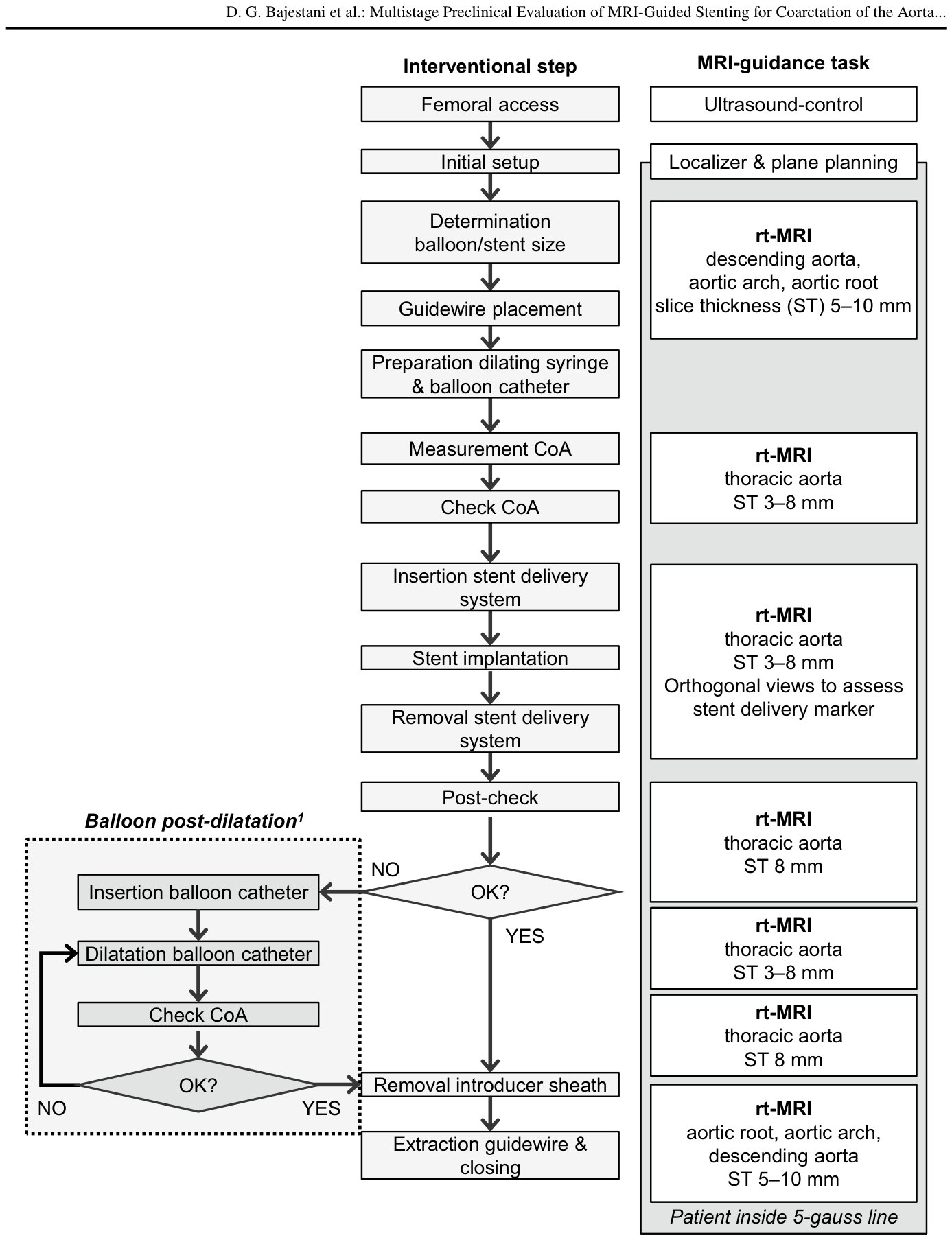
Figure 4. Fig. 4 Flow diagram of the MRI-guided CoA interventional work- flow performed during the Stage 2 phantom and Stage 3 in vivo experiments. 1 Balloon post-dilatation was performed in one animal解説: 第2段階のファントム実験と第3段階の生体モデル実験で実施されたMRIガイド下大動脈縮窄症介入のワークフロー図です。介入ステップとMRIガイドタスクが示されており、大動脈縮窄症の評価、ガイドワイヤーの配置、ステント留置、およびバルーン拡張の手順が含まれています。バルーン拡張後処置は第3段階の1頭の動物で行われたことも明記されています。
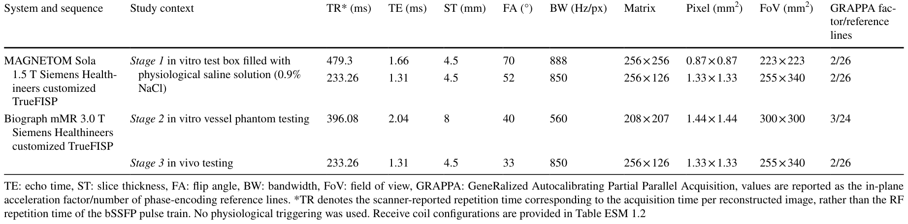
Table 1. Table 1 MRI sequences used during the three evaluation stages解説: 3つの評価段階で使用されたMRIシーケンスのパラメータが示されています。各段階(ステージ1のin vitroテストボックス、ステージ2のin vitro血管ファントムテスト、ステージ3のin vivoテスト)で使用されたMRIシステムとシーケンス、TR(繰り返し時間)、TE(エコー時間)、ST(スライス厚)、FA(フリップ角)、BW(帯域幅)、マトリックス、ピクセルサイズ、FoV(視野)、GRAPPA因子/参照ラインなどの詳細な情報がまとめられています。
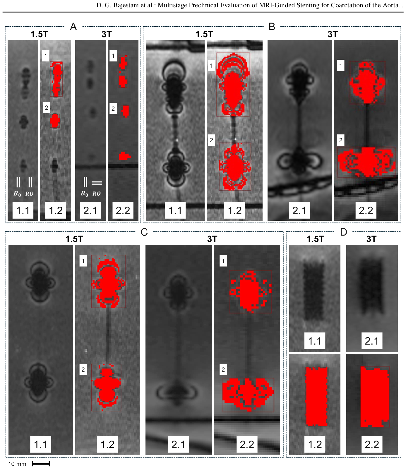
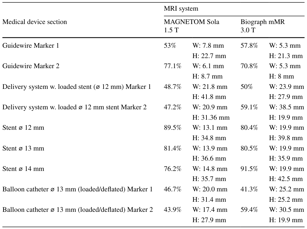
また、発生するアーチファクト(画像上の偽像)の寸法も分析されました。
Figure 3. Fig. 3 MR images of the MR Conditional guidewire (A), stent deliv- ery system with crimped nitinol stent (B), balloon catheter (C), and expanded nitinol stent (D) with corresponding MATLAB-based arti- fact evaluations (red overlays). Imaging was performed at 1.5 T and 3.0 T. Panels A1.1–D1.1 show images acquired at 1.5 T and panels A2.1–D2.1 at 3.0 T; adjacent panels (A1.2–D2.2) illustrate the cor- responding artifact analyses. Red rectangles indicate bounding boxes and red pixels identified artifact regions. Artifacts are labeled according to their numbering in Table 2. In panel A, white line pairs labeled B0 and RO indicate the orientations of the main magnetic解説: MRコンディショナルガイドワイヤー(A)、ニッケルチタン合金製ステントが装着されたステントデリバリーシステム(B)、バルーンカテーテル(C)、および拡張されたニッケルチタン合金製ステント(D)のMR画像と、それに対応するMATLABベースのアーチファクト評価(赤色のオーバーレイ)を示しています。画像は1.5テスラと3.0テスラで取得され、A1.1-D1.1が1.5テスラ、A2.1-D2.1が3.0テスラで、隣接するパネル(A1.2-D2.2)は対応するアーチファクト分析を示しています。赤い長方形がバウンディングボックスを、赤いピクセルが識別されたアーチファクト領域を示しています。
第2段階:ファントムを用いた手技の評価
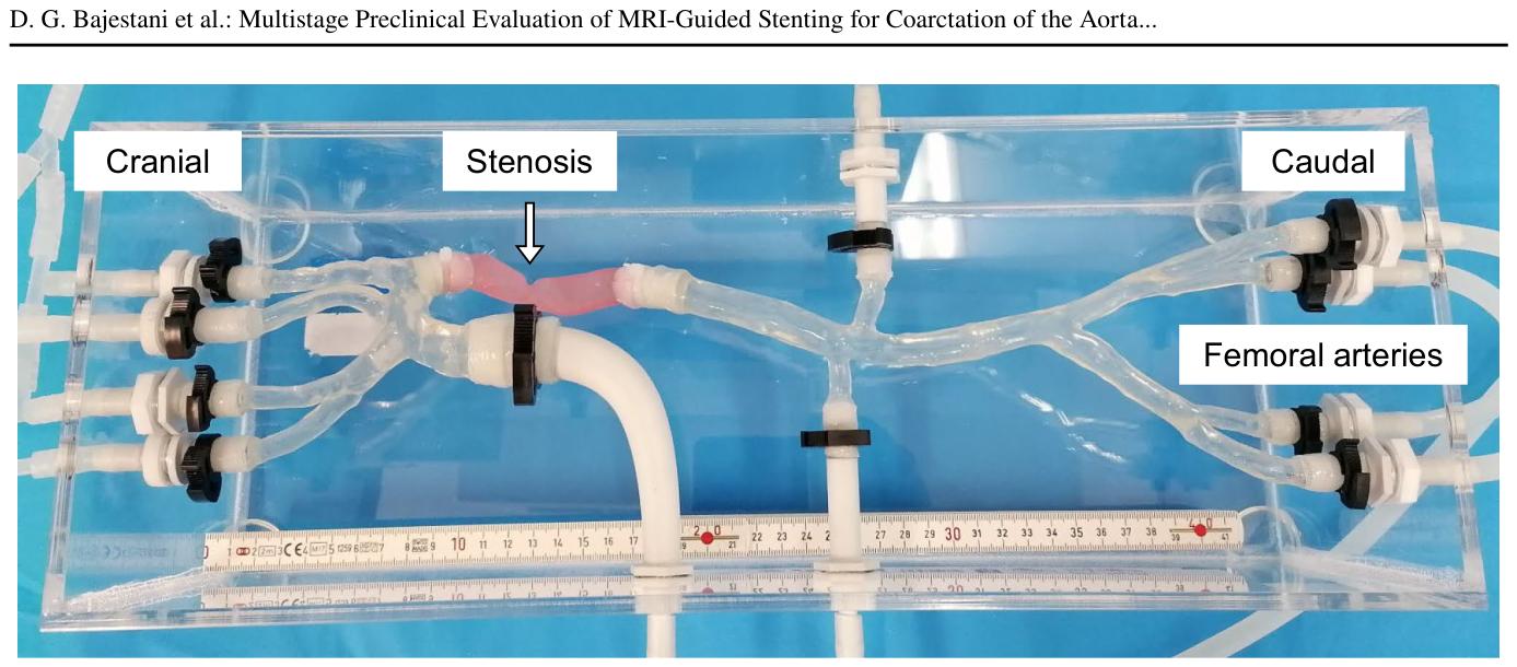
ヒトのMRIスキャンデータに基づいた、大動脈縮窄症をシミュレートするポリマー製の血管ファントム(
Figure 2. Fig. 2 Scan-data-based polymer vessel phantom for testing MRI-guided catheter-based stenting and balloon dilatation. An incorporated stenosis (white arrow) simulates coarctation of the aorta (CoA) and allows controlled placement and removal of stents within the descending aorta解説: MRIスキャンデータに基づいたポリマー製血管ファントムで、MRIガイド下のカテーテルによるステント留置術とバルーン拡張術のテストに使用されました。組み込まれた狭窄(白い矢印)が大動脈縮窄症(CoA)をシミュレートし、下行大動脈内でのステントの制御された配置と除去を可能にします。この図は、ファントムの全体構造と主要な血管を示しており、頭側、尾側、大腿動脈が示されています。
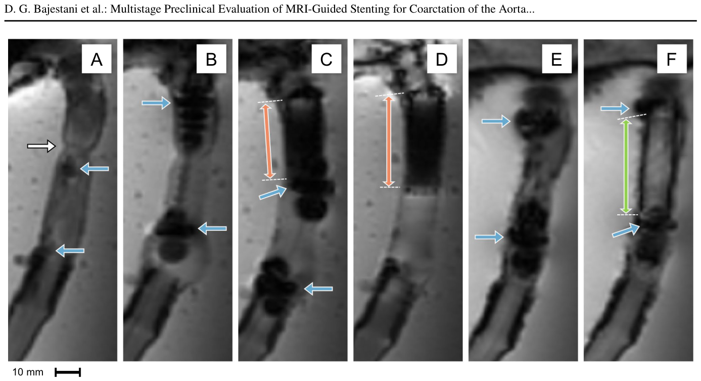
Figure 5. Fig. 5 MRI-guided minimally invasive CoA intervention within the in vitro vessel phantom using an MR Conditional guidewire, stent delivery system and balloon catheter. (A): Probing of the steno- sis (white arrow) of the descending aorta using the MR Conditional guidewire (passive markings indicated by blue arrows). (B): Position- ing of the stent delivery system over the wire using passive markings of the delivery system (blue arrows). (C): Delivered stent inside the stenosis (orange double-headed arrow) with the stent delivery system after deployment (passive markings indicated by blue arrows). (D):解説: MRコンディショナルガイドワイヤー、ステントデリバリーシステム、およびバルーンカテーテルを用いた、生体外血管ファントム内でのMRIガイド下低侵襲大動脈縮窄症介入の様子です。(A)MRコンディショナルガイドワイヤーを用いた下行大動脈の狭窄(白い矢印)のプロービング。(B)デリバリーシステムの受動的マーキング(青い矢印)を用いてワイヤー上でステントデリバリーシステムを配置。(C)留置されたステント(オレンジ色の両方向矢印)とデリバリーシステム(青い矢印)。(D)留置されたステント。(E)受動的マーキング(青い矢印)を用いて配置されたバルーンカテーテル。(F)バルーン拡張中のガドリニウム充填バルーンカテーテル(緑色の両方向矢印)。
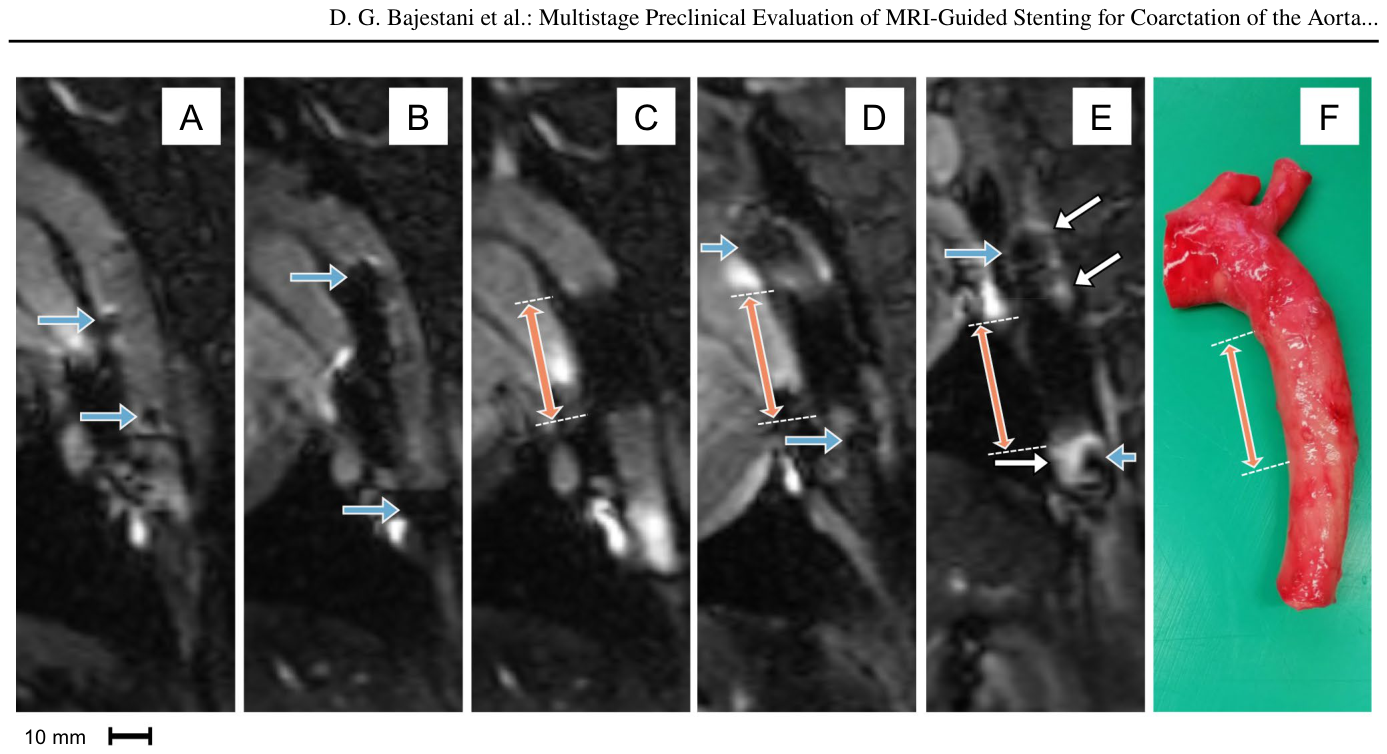
Figure 6. Fig. 6 MRI-guided minimally invasive CoA intervention in an in vivo porcine model using an MR Conditional guidewire, research prototype stent delivery system, and research prototype balloon cath- eter. (A): Probing of the descending aorta using the MR Conditional guidewire (passive markings indicated by blue arrows). (B): Posi- tioning of the stent delivery system over the guidewire using passive markings (blue arrows). (C): Deployed stent inside the descending aorta (orange double-headed arrow). (D): Deployed stent inside the descending aorta (orange double-headed arrow) and balloon cath- eter positioned using passive markings (blue arrows). (E): Balloon解説: MRコンディショナルガイドワイヤー、研究プロトタイプステントデリバリーシステム、および研究プロトタイプバルーンカテーテルを用いた生体モデル(ブタ)におけるMRIガイド下低侵襲大動脈縮窄症介入の様子です。(A)MRコンディショナルガイドワイヤー(青い矢印)を用いた下行大動脈のプロービング。(B)受動的マーキング(青い矢印)を用いてガイドワイヤー上にステントデリバリーシステムを配置。(C)下行大動脈内に展開されたステント(オレンジ色の両方向矢印)。(D)展開されたステント(オレンジ色の両方向矢印)と、受動的マーキング(青い矢印)を用いて配置されたバルーンカテーテル。(E)ステント留置されたセグメント内でのバルーン拡張中のガドリニウム系溶液で満たされたバルーンカテーテル(オレンジ色の両方向矢印)と、その結果生じるMRI信号増強(白い矢印)。(F)移植された下行大動脈と埋め込まれたニッケルチタン合金製ステント(オレンジ色の両方向矢印で強調)。
Table 2. Table 2 Artifact size evaluation of the interventional device set for MRI-guided CoA intervention based on ASTM F2119-07, including proportional artifact coverage (artifact pixels relative to bounding box area) and bounding box dimensions (width W, height H)解説: MRIガイド下大動脈縮窄症介入のための介入デバイスセットのアーチファクトサイズ評価を示しており、ASTM F2119-07に基づいています。評価はMAGNETOM Sola 1.5テスラとBiograph mMR 3.0テスラのMRIシステムで行われ、ガイドワイヤー、ステントが装填されたデリバリーシステム、ステント、バルーンカテーテルといった各デバイスセクションごとのアーチファクトピクセルがバウンディングボックス面積に占める割合(プロポーショナルアーチファクトカバレッジ)と、バウンディングボックスの寸法(幅W、高さH)がまとめられています。
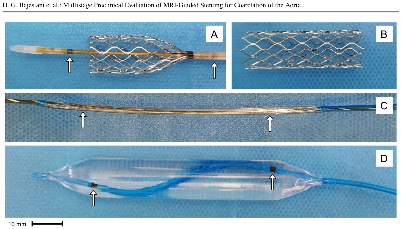
Figure 1. Fig. 1 Research prototype nitinol stent during deployment from the stent delivery system (A). Fully expanded ⌀ 12 mm nitinol stent (B), research prototype balloon catheter with inserted guidewire in the解説: 研究プロトタイプのニッケルチタン合金製ステントがデリバリーシステムから展開されている様子(A)。完全に拡張された直径12mmのニッケルチタン合金製ステント(B)。ガイドワイヤーが挿入された収縮状態の研究プロトタイプバルーンカテーテル(C)。0.9%生理食塩水で満たされ完全に膨張したバルーンカテーテル(D)を示しています。白い矢印は組み込まれたMR可視マーカーを示しています。
コメントを残す